
Emulate3D Controls Testing for Machine Builders
Virtual Commissioning Models Built Directly in Your CAD Environment
Emulate3D CiTIM (CAD is The Model) for Machine Builders helps you create controls testing models of a wide range of machine types, directly within PTC Creo, SOLIDWORKS, and Autodesk Inventor. Debug and refine the kinematic sequences and timing of your designs in a virtual environment, and make changes to them faster than is possible with physical prototypes.
Create your machine or mechanical system in CAD, mark up the various kinematic and control elements, add a load source if the operation is triggered by the presence of products, then connect the control and activation elements to the PLC IO and run the emulation model.
By combining mechanical CAD information with real control system logic you can create a valuable testbed in the form of a Dynamic Digital Twin.
View and verify the system operation and control logic before you commit expenditure to building the real thing. Use the controls HMI to train operators offline, and with no disruption to running operations. Create system failures that would be costly or dangerous in the real world, and develop start up and recovery sequences that would be problematic outside the virtual environment.
The benefits of dynamic virtual prototyping using Emulate3D for Machine Builders include:
- - Faster automation project development
- - Thorough logic sequence and timing verification
- - Eliminate or reduce costly physical prototypes
- - Effective and non-disruptive user training
The successful operation of a machine or other automated system results from a combination of the mechanical design expressed in CAD, and the logical control. Emulate3D for Machine Builders is a virtual testing environment which brings these two definitions together, and provides a means of testing and refining the solution in a cost-effective, repeatable way.
The goals of CAD is the Model are as follows:
- Always use the latest CAD model and PLC logic
- Create a straightforward combination of CAD and logic
- Reduce the time it takes to test incremental changes
- Support existing workflows whenever possible
Implementing CAD is the Model in your preferred CAD system
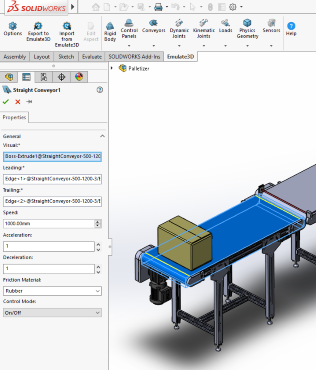
CAD is the Model is designed to be a process that fits easily with your existing workflow – it is additive rather than intrusive. Once you have created your mechanical system in CAD, you switch to the Emulate3D add-in ribbon and mark up your CAD using the ribbon elements created for your application. The process of marking up CAD elements enables them to be recognized automatically as control or activation elements in the Emulate3D runtime environment, and behave appropriately.
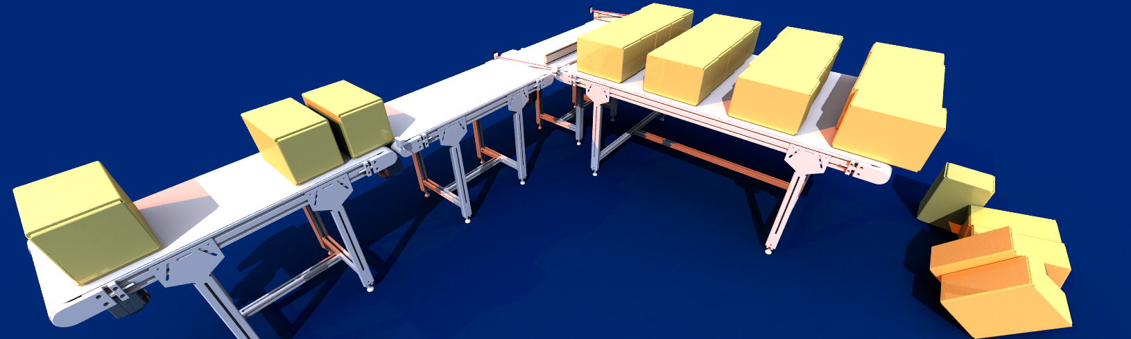
Conveyors are defined as having a leading edge and a trailing edge, and you can add default values such as a running speed, an acceleration and deceleration, and the material the belt is made of. Photo eyes are active elements which connect to PLC inputs or control scripts. The pusher has a direction, a start position and a range of movement, and you can define default values for the pusher movement velocity.
While some ribbon elements may be equally useful to a wide range of users, the power of the CAD is the Model approach is that company-specific elements are easy to create, so your ribbon contains all the elements you need to mark up your models, and your company workflow is accommodated.
Connecting the active control elements in your model to your PLC logic uses a spreadsheet to map the PLC IO to the model control elements, through the Tag Browser. This action is performed once, and then the IO mapping can be included within the model structure. Subsequent CAD modifications can be carried out and the model regenerated without disrupting the rest of the model, accelerating your development schedule.
The Power of Aspects
CAD is the Model uses the concept of Aspects to add functionality to your CAD model. Aspects are properties which inform the runtime environment of the behaviors associated with the CAD element. Aspects are an efficient means of adding functionality to CAD, they can be user-defined, and are easily added.
Typical Aspects encountered within a material handling model might include:
- Collision geometry physics types such as box, mesh, sphere, cylinder, etc
- Kinematic joints such as hinge, slider, etc
- CAD graphics mesh
- Movement surfaces like conveyors
- Sensors which could include functions like OnBlocked, OnCleared, etc
- Load creators with a release interval parameter
- Tool Center Point for robot modelling
You can create Aspects to add to your ribbon, and you can have multiple Aspects associated with a visual (a model object) if that’s what your workflow requires. Aspects are created as C# Aspect scripts within Emulate3D, then read into the CAD product as an Add-In Emulate3D ribbon. Your marked up CAD elements retain the Aspects within the CAD files, along with the IO/model mapping, and the runtime Emulate3D model imports them and generates the virtual commissioning model.
Currently CAD is the Model is implemented in PTC Creo, SOLIDWORKS, and Autodesk Inventor. You can implement the same approach within most Emulate3D products by importing your CAD from other systems and using the CITM toolbar to add and parametrize Aspects.
Emulate3D is a SOLIDWORKS Authorised Development Partner
CAD is the Model is currently available as a SOLIDWORKS Addin which outputs suitably marked-up CAD as Virtual Commissioning models connected to PLCs or higher level controllers, or alternately as kinematic models ready to be driven by internal scripting.
